Peter Apps
Peter Apps
AP Physics C: E&M 💡
26 resourcesSee Units
2.3: Dielectrics
What are Dielectrics?
Dielectrics are insulating materials that are often used in capacitors to increase their capacitance. They help solve the problem of how to get more charge into a capacitor without having the voltage decrease.
Let's look back at the equation for capacitance from section 2.2:
Modifying the equation to include a dielectric involves adding a new term k, which is the dielectric constant. In general, the easier a material is to polarize, the higher it's dielectric constant is. The molecules in an insulating material can become partially or fully polarized, depending on the material's "dielectric constant," a physical property that ranges from 1 to higher values. This degree of polarization determines how much the material can affect the electric field between the plates of a capacitor. You don't have to memorize these for the AP exam, but the values for common dielectrics are shown below:
Common Dielectrics:
| Dielectric constant k | |
| Vacuum | 1 |
| Air | 1.00059 |
| Bakelite | 4.9 |
| Fused Quartz | 3.78 |
| Neoprene Rubber | 6.7 |
| Nylon | 3.4 |
| Paper | 3.7 |
| Polystyrene | 2.56 |
| Pyrex Glass | 5.6 |
| Silicon Oil | 2.5 |
| Strontium Titanate | 233 |
| Teflon | 2.1 |
| Water | 80 |
Data obtained from lumenlearning.com
In each of these equations, notice that if we have a vacuum, or air, between the plates in the capacitor, the equations return to the same form as we found in 2.2.
Why Does Adding a Dielectric Increase the Capacitance?
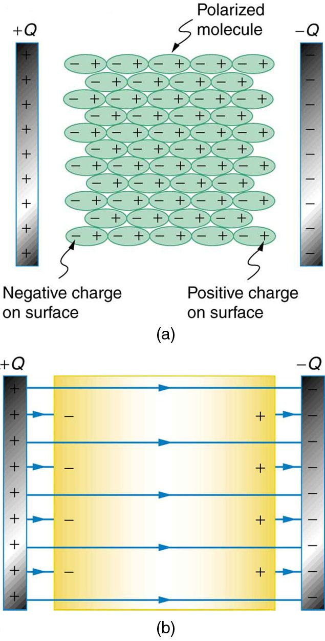
Great question! It's because a dielectric becomes polarized easily. In fact, the easier the dielectric becomes polarized, the greater its k becomes. Let's look at an image to understand why the polarization helps increase the capacitance.

Image from opentextbc.ca
In image (a), we can see that the molecules of the dielectric become polarized and align opposing the charge on the plates. This produces a layer of opposite charge on the surface of the dielectric that attracts more charge onto the plate, because of Coulomb's Law, increasing its capacitance.
Another way to understand how a dielectric increases capacitance is to look at how it changes the electric field inside the capacitor. Image (b) shows the electric field lines with a dielectric in place. Since some of the field lines end on charges in the dielectric (because the polarity of the dielectric is opposite that of the plates), the overall field between the plates is weaker than if there were a vacuum between the plates, even though the same charge is on the plates.
The voltage between the plates is V = Ed, so it is also reduced by the dielectric. This means there is a smaller V for the same charge Q and since C = Q/V, the capacitance is greater.
When a dielectric material is placed between the plates of a capacitor, it becomes partially polarized and generates an electric field within itself. The overall electric field between the plates is the combination of the field between the plates and the field induced in the dielectric material. This combined field is always weaker than the field between the plates alone, resulting in a decrease in the potential difference between the plates.
Practice Question
(image for the FRQ is located below the prompts)
A capacitor consists of two conducting, coaxial, cylindrical shells of radius a and b, respectively, and length L >> b. The space between the cylinder is filled with oil that has a dielectric constant k. Inititally both cylinders are uncharged, but then a battery is used to charge the capactior, leaving a charge +Q on the inner cylinder and -Q on the outer cylinder, as shown above. Let r be the radial distance from the axis of the capacitor.
(a) Using Gauss's Law, determine the electric field midway along the length of the cylinder for the following values of r, in terms of the given quantities and fundamental constants. Assume end effects are neglible.
i. a < r < b
ii. b < r << L
(b) Determine the following in terms of the given quantities and fundamental constants.
i. The potential difference across the capacitor.
ii. The capacitance of this capacitor.

Image from collegeboard.org
a)
- i. Use Gauss' Law. Remember to include the k since we have a dielectric.
- Outside the outer shell, we enclose the total charge from both shells. Q_enc = +Q - Q = 0, so then E =0.
b)
- i. Plug into the integral form of potential difference equation.
- ii. Plug into the Capacitance equation
Browse Study Guides By Unit
⚡️Unit 1 – Electrostatics
🔋Unit 2 – Conductors, Capacitors, Dielectrics
🔌Unit 3 – Electric Circuits
🧲Unit 4 – Magnetic Fields
⚛️Unit 5 – Electromagnetism
✍️Exam Skills- FRQ/MCQ
🙏Exam Reviews

© 2023 Fiveable Inc. All rights reserved.